×
![Enlarged Image]()
Integrated Computational Materials Engineering (ICME)
Internal State Variable (ISV) model
Overview
We describe the macroscale model which includes the kinematics, damage progression equations, and the elastic-plastic framework. This model is used in the performance analysis of the main bearing cap.Kinematics of the Macroscale Model
The deformation gradient, (F) is multiplicatively decomposed into the isochoric inelastic, or plastic (Fpd), dilatational inelastic (Fpv), and elastic parts (Fe) [Davison et al., 1977; Bammann and Aifantis, 1989; Bammann et al., 1993, Horstemeyer et al., 2000] as shown of Figure 1. The decomposition is given by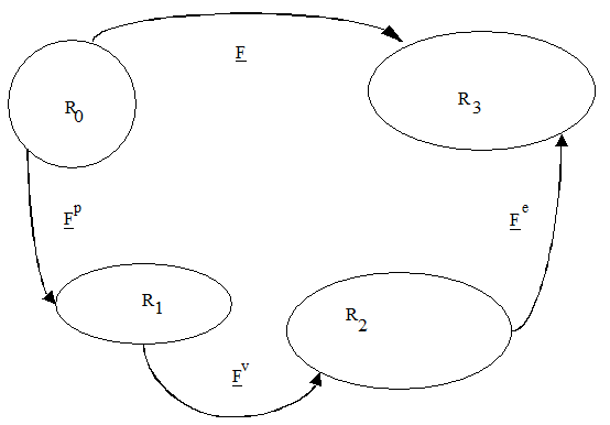
Figure 1 Multiplicative decomposition of the deformation gradient
The volumetric inelastic deformation gradient Fpv, is assumed to have the form Fpv = ΦI, where Φ is a function to be determined from kinematics (or conservation of mass).
The Jacobian of Eq. (6.1) is related to the change in volume or change in density for constant mass as
where Φ is the damage variable.
The velocity gradient associated with the deformation gradient
where
and
The deformation rate D is additively decomposed into an elastic part and plastic part (volumetric and deviatoric).
The plastic volumetric rate of deformation is defined as
Also note here that Fpv vanishes. The trace of the volumetric part (Eq. (6.9)) is given as
The formulation of damage Φ is described in terms of void nucleation and void growth in the unstressed intermediate configuration:
Where vv is the void average volume and η the number of voids per unit volume or void nucleation density in the intermediate configuration
Void Nucleation, Growth, and Coalescence Aspects
The process of ductile fracture of most metals and alloys occurs mainly due to the void nucleation, growth and finally coalescence into a micro-crack (Figure 2). If the extent of void growth up to fracture is small, it is possible to ignore its effects on the constitutive equations. However, a realistic model on ductile fracture prediction must include void nucleation, void growth and a condition for void coalescence.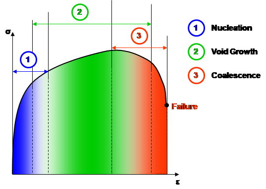
Figure 2 – Sequences in a ductile fracture mechanism.
The damage formulation is shown conceptually in Figure 3. The number density of voids can change and growth of voids can occur independently or simultaneously.
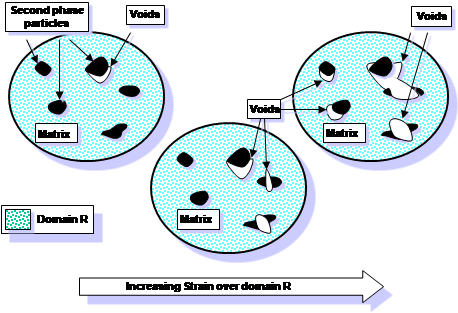
Figure 3 – Schematic of fictitious material with increasing void nucleation density and void growth to be captured conceptually in a fracture prediction model.
Void Nucleation
The void nucleation rule of Horstemeyer and Gokhale [1999] is used to model the results from the experimental data under compression, tension, and torsion. The integrated form of the void nucleation rate equation is given by(A.30) where η(t) is the void nucleation density, ε is the strain at time t, Ccoeff is a material constant. T is temperature in the absolute scale, and CTh is the temperature dependent material constant determined from experiments. The volume fraction of the second phase material is f, the average silicon particle size is d, and the bulk fracture toughness is KIC. The material parameters a, b, and c relate to the volume fraction of nucleation events arising from local microstresses in the material. These constants are determined experimentally from tension, compression, and torsion tests in which the number density of void sites is measured at different strain levels. The stress state dependence (compression, tension, and torsion) on damage evolution is captured in Eq. (6.17) by using the three stress invariants denoted by I1, J2, and J3, respectively [Horstemeyer and Gokhale, 1999].
Void Growth
A crucial feature in determining the damage state, besides nucleation of voids, is void growth. Several void growth models are considered. The first one by McClintock [1968] is given in terms of the void radius asIn Eq. (6.18) the void volume grows as the strain and/or stress triaxiality increases. The material constant n is related to the strain hardening exponent and is determined from the tension tests. R0 is taken to be the initial radius of the voids.
Another void growth model in terms of void radius is given by Rice and Tracey [1969] is given byAnother void growth model by Budiansky et al. [1982] in terms of void volume rate is given by
The last one worth mentioning in this context is that by Cocks and Ashby [1980] given in terms of the void volume fraction rate,
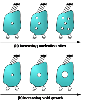
Figure 4 – The damage model encompasses the limiting cases shown by (a) just void nucleation in and (b) a single void growth.
Void Coalescence
Coalescence is the joining of voids either at the microscale or macroscale and has been observed to occur by two main mechanisms: Natural coalescence: two neighboring voids grow together until they join as one [Garber et al., 1976] as illustrated in Figure 5. Void sheet mechanism: a localized shear band occurs between neighboring voids [Cox and Low, 1974, Rogers, 1960]. Coalescence can be thermodynamically added to the damage framework described in Eq. (A.35). It arises naturally with the multiplicative relation between the nucleation and growth terms:which gives
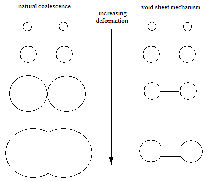
Figure 5 – Two different coalescence mechanisms observed in various materials.
In the limiting case when the function in Eq. (A.35) equals zero, simple coalescence occurs. In this case, the model reflects the growing of two voids into one. When , microvoid linking is reflected and the rate of damage is increased [Garrison and Moody, 1987].
The dependence on dendrite cell size (DCS) is based on the work of Major et al. [1994], who noted a dependence of the elongation to failure with DCS.
The constant CTC is characterizes the temperature dependence of the coalescence term based on a multitude of mesomechanical simulations.
Where σ is the stress tensor, εe is the elastic strain, Ce is the elastic stiffness, and the elastic Lame constants, and ξ a material parameter.
The flow rule is given by:
where denotes the deviatoric stress tensor, and the plastic normal tensor defined as
The plastic flow rule can be inverted to
This constitutive relation clearly shows the decomposition of the stress as the sum of the yield stress , the isotropic hardening , the kinematic hardening , and a viscosity term, often called the viscous stress (Figure 6).
Visco-Elastoplasticity Aspects
The internal state variable (ISV) plasticity model [Bammann et al., 1993] is modified to account for stress state dependent damage evolution.Elastic Relation
The elastic relation is given by,Where σ is the stress tensor, εe is the elastic strain, Ce is the elastic stiffness, and the elastic Lame constants, and ξ a material parameter.
Flow Rule
The deviatoric inelastic flow rule, , encompasses the regimes of creep and plasticity and is a function of the temperature , the kinematic hardening internal state variable , the isotropic hardening internal state variable , the volume fraction of damaged material , and the functions , , and , which are related to yielding with Arrhenius-type temperature dependence (Table A.7).The flow rule is given by:
where denotes the deviatoric stress tensor, and the plastic normal tensor defined as
The plastic flow rule can be inverted to
This constitutive relation clearly shows the decomposition of the stress as the sum of the yield stress , the isotropic hardening , the kinematic hardening , and a viscosity term, often called the viscous stress (Figure 6).
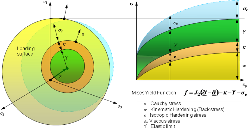
Figure 6 – Decomposition of the stress tensor into a yield, isotropic hardening, kinematic hardening and viscous stresses.
Hardening Rule
The hardening may be defined as the increase in yield stress due to plastic deformation. For hardening materials, the yield surface will evolve in space in one of three ways:The first form of yield surface evolution is called isotropic hardening κ, which reflects the effect of the global dislocation density. For isotropic hardening, the yield surface grows in size while the center remains at a fixed point in stress space (Figure 7).
The second form of yield surface evolution is called kinematic hardening α, also called Bauschinger effect (Figure 7), which reflects the effect of anisotropic dislocation density. For kinematic hardening, the center of the yield surface translates in stress space, while the size remains fixed. For both isotropic and kinematic hardening, the orientation of the yield surface remains fixed.
The third type of yield surface evolution is called mixed hardening where both isotropic and kinematic hardening characteristics are evident. For mixed hardening, the orientation (not considered here) of the yield surface may also change as well.
Although isotropic hardening is the most common form of yield surface evolution assumed in finite element models for metal forming simulation, it is not necessarily the most accurate. The mixed hardening model is most likely the most accurate of the three models.
The evolution of the kinematic hardening is defined by:
The evolution of the isotropic hardening is defined by:
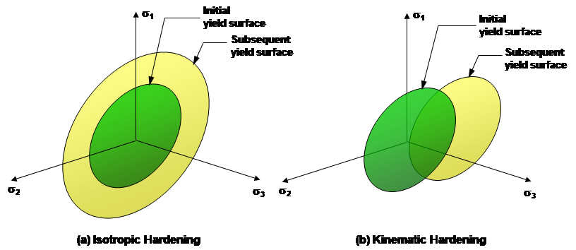
Figure 7 – Evolution of the yield surface in case of (a) isotropic hardening and (b) kinematic hardening.
Material Parameter
The BCJ Plasticity material parameters (Table 1), which are Arrhenius-type or linear function of temperature T. A fitting software, DMGfit, developed at MSU based on the ISV plasticity-damage model (DMG) and described in Section D.3, is used to determine the plasticity and damage constants for the model to simultaneously fit tension, compression, and torsion stress-strain curves at different temperatures and strain rates.Table 1 – Material parameters of BCJ-Plasticity.
| Mechanism | Description | Term Definition |
|---|---|---|
| Yield Stress | Rate-Independent Yield Stress | |
| Magnitude of Rate-Dependence on yielding | ||
| Rate-Dependence on Initial Yielding | ||
| Kinematic Hardening | Modulus | |
| Dynamic Recovery | ||
| Static Recovery | ||
| Isotropic Hardening | Modulus | |
| Dynamic Recovery | ||
| Static Recovery |
| Component Definition | SDV |
|---|---|
| Kinematic Hardening b11 | Statev(1) |
| Kinematic Hardening b22 | Statev(2) |
| Kinematic Hardening b33 | Statev(3) |
| Kinematic Hardening b12 | Statev(4) |
| Kinematic Hardening b13 | Statev(5) |
| Kinematic Hardening b23 | Statev(6) |
| Isotropic Hardening κ | Statev(7) |
| Temperature | Statev(8) |
| Effective Plastic Strain | Statev(9) |
| McClintock Void Growth (second phase pores) | Statev(10) |
| Rate of Change of M Porosity | Statev(11) |
| Stress Triaxiality | Statev(12) |
| Nucleation | Statev(13) |
| Damage | Statev(14) |
| Nucleation Rate | Statev(15) |
| Damage Rate | Statev(16) |
| Nucleation from previous time step | Statev(17) |
| Cocks-Ashby (CA) Void Growth (large pores) | Statev(18) |
| Rate of Change of CA Porosity | Statev(19) |
| Kinematic Hardening α11 | Statev(20) |
| Kinematic Hardening α22 | Statev(21) |
| Kinematic Hardening α33 | Statev(22) |
| Kinematic Hardening α12 | Statev(23) |
| Kinematic Hardening α13 | Statev(24) |
| Kinematic Hardening α23 | Statev(25) |
| blank | Statev(26) |
Material Parameters
| Constant Definition | PROPS | Constant Definition | PROPS |
|---|---|---|---|
| Shear Modulus G0 | Props(1) | Initial Temperature T0 | Props(28) |
| a | Props(2) | Heat Generation Coefficient | Props(29) |
| Bulk Modulus K0 | Props(3) | McClintock Damage Constant n | Props(30) |
| b | Props(4) | Initial Void Radius | Props(31) |
| Melting Temperature Tmelt | Props(5) | Torsional constant a (nucleation) | Props(32) |
| BCJ Plasticity Parameter c01 | Props(6) | Tens/Comp constant b (nucleation) | Props(33) |
| BCJ Plasticity Parameter c02 | Props(7) | Triaxiality constant c (nucleation) | Props(34) |
| BCJ Plasticity Parameter c03 | Props(8) | Coeff. constant c (nucleation) | Props(35) |
| BCJ Plasticity Parameter c04 | Props(9) | Fracture Toughness KIC (nucleation) | Props(36) |
| BCJ Plasticity Parameter c05 | Props(10) | Average Particle Size (nucleation) | Props(37) |
| BCJ Plasticity Parameter c06 | Props(11) | Particle Volume Fraction (nucleation) | Props(38) |
| BCJ Plasticity Parameter c07 | Props(12) | Nearest Neighbor distance (coal.) | Props(39) |
| BCJ Plasticity Parameter c08 | Props(13) | Chi Exponent (coalescence) | Props(40) |
| BCJ Plasticity Parameter c09 | Props(14) | Reference Dendrite Cell size DCS0 | Props(41) |
| BCJ Plasticity Parameter c10 | Props(15) | Dendrite Cell size DCS | Props(42) |
| BCJ Plasticity Parameter c11 | Props(16) | Dendrite Cell size Exponent zz | Props(43) |
| BCJ Plasticity Parameter c12 | Props(17) | Initial Void Volume Fraction for CA | Props(44) |
| BCJ Plasticity Parameter c13 | Props(18) | BCJ Plasticity Parameter c21 | Props(45) |
| BCJ Plasticity Parameter c14 | Props(19) | BCJ Plasticity Parameter c22 | Props(46) |
| BCJ Plasticity Parameter c15 | Props(20) | BCJ Plasticity Parameter c23 | Props(47) |
| BCJ Plasticity Parameter c16 | Props(21) | BCJ Plasticity Parameter c24 | Props(48) |
| BCJ Plasticity Parameter c17 | Props(22) | BCJ Plasticity Parameter c25 | Props(49) |
| BCJ Plasticity Parameter c18 | Props(23) | BCJ Plasticity Parameter c26 | Props(50) |
| BCJ Plasticity Parameter c19 | Props(24) | Nucleation Temperature Dependence | Props(51) |
| BCJ Plasticity Parameter c20 | Props(25) | Elastic Modulus Porosity Exponent β | Props(52) |
| BCJ Plasticity Parameter ca | Props(26) | Flag to use vvfr.dat file (0=no,1=yes) | Props(53) |
| BCJ Plasticity Parameter cb | Props(27) | Cacon | Props(54) |
User Material Subroutine UMAT for Plasticity-Damage Model
The internal state variable plasticity-damage model (DMG) is implemented in the user material subroutine UMAT of Abaqus/Standard. The state-dependent variables (SDV) and material constants are respectively defined in Tables 2 and 3.Examples of Abaqus input files and ISV user material
References
- Abaqus Analysis User’s Manual, Version 6.8, Dassault Systemes Simulia Corp., Providence, RI, USA, 2008.
- Bammann, D.J., and Aifantis, E.C., “A Damage Model for Ductile Metals,” Nuclear Engng. Design, Vol. 116, 1989, pp. 355–62.
- Bammann, D. J., "Modeling Temperature and Strain Rate Dependent Large of Metals," Applied Mechanics Reviews, Vol. 43, No. 5, Part 2, May, 1990.
- Bammann, D. J., Chiesa, M. L., Horstemeyer, M. F., Weingarten, L. I., "Failure in Ductile Materials Using Finite Element Methods," Structural Crashworthiness and Failure, eds. T. Wierzbicki and N. Jones, Elsevier Applied Science, The Universities Press (Belfast) Ltd, 1993.
- Budiansky, B., Hutchinson, J.W., and Slutsky, S., “Void Growth and Collapse in Viscous Solids,” In: H.G. Hopkins and M.J. Sowell, Editors, Mechanics of Solids, The Rodney Hill 60th Anniversary Volume, Pergamon, 1982, pp. 13–45.
- Cox, T.B., and Low Jr, J.R., “An Investigation of the Plastic Fracture of AISI 4340 and 18 Nickel-200 Grade Maraging Steels, Metall. Trans. Vol. 5, 1974, pp. 1457–1470.,
- Davison L., Stevens, A.L., and Kipp, M.E., “Theory of Spall Damage Accumulation in Ductile Metals,” J. Mech. Phys. Solids, Vol. 25, 1977, pp. 11–28.
- Garber, R., Bernstein, I.M., and Thompson, A.W., “Effect of Hydrogen on Ductile Fracture of. Spheroidized Steel,” Scripta Metall., Vol. 10, 1976, pp. 341–345.
- Garrison, W.M., and Moody, N.R., “Ductile Fracture,” J. Phys. Chem. Solids , Vol. 48, No. 11, 1987, pp. 1035–1074.
- Hayhurst, D.R., Leckie, F.A., and McDowell, D.L., “Damage Growth Under Nonproportional Loading,” ASTM Special Technical Publication (STP), 853, 1985, pp. 688–699.
- Horstemeyer, M.F. and Gokhale, A.M., “A Void-crack Nucleation Model for Ductile Material,” Int. J. Solids Struct., Vol. 36, 1999, pp. 5029–5055.
- Horstemeyer, M.F., Lathrop, J., Gokhale, A.M., and Dighe, M., “Modeling Stress State Dependent Damage Evolution in a Cast Al-Si-Mg Aluminum Alloy,” Theoretical and Applied Fracture Mechanics, Vol. 33, 2000, pp. 31-47.
- Horstemeyer, M. F., Baskes, M. I., and Plimpton, S. J., “Computational Nanoscale Plasticity Simulations Using Embedded Atom Potentials,” Prospects in Mesomechanics, ed. George Sih, Theoretical and Applied Fracture Mechanics, Vol. 37, No. 1–3, 2001, pp. 49–98.
- Lathrop, J.F., BFIT – A Program to Analyze and Fit the BCJ Model Parameters to Experimental Data Tutorial and User’s Guide. SANDIA REPORT SAND97-8218 . UC-405, Unlimited Release, Printed December 1996.
- McClintock, F.A., “A Criterion for Ductile Fracture by the Growth of Holes,” J. App. Mech. Trans. ASME, Vol. 35, 1968, pp. 363–371.
- Analytic Theory of Fatigue. The Trend in Engineering, Vol. 13, 1961, pp. 9–14.
- Rice, J.R., and Tracey, D.M., “On the Enlargement of Voids in Triaxial Stress Fields,” J. Mech. Phys. Sol., Vol. 17, 1969, pp. 201–217.
- Rogers, H.C., “The Tensile Fracture of Ductile Metals,” Trans. AIME, Vol. 218, pp. 498–506, 1960.
